What types of power meters are there?
The two essential components of a power meter are:
- Power Sensor
- Power Indicator
The power sensor is also identified as a power meter probe that converts high-frequency electrical signals into electrical signals that can be easily detected through energy—the purpose of power indicators in signal amplification, conversion, and display. The display directly presents the power value. Different power levels and transmission line structures should be present to deal with multiple frequencies.
Classification by connection method:
RF and microwave power meters can be classified into two types based on different connection methods in the test system:
- Terminal type
- Pass-through type.
The terminal type power meter employs the power meter probe as the terminal load of the system. The power to be measured is absorbed by the power meter, and the power indicator observes the value. Small signals test usually require terminal power meters. The characteristic of the terminal power meter are:
- On comparison between RF and microwave power measurement instruments, the terminal type power tops the list as it offers significant accuracy in amplitude measurements.
- The device is unable to measure high power. The upper limit is +20dBm, and the lower limit is -60dBm
- (3) The various modulated signals’ average power, peak power, burst power, etc., can be measured.
When talking about the pass-through power meter, a specific coupling device is present that couples a part of the power from the transmitted power according to a certain proportion. Then, it is sent to the power meter for measurement. Multiply the indicated value by the scaling factor to get the total power transmitted. The main features of the pass-through power meter are:
- It exhibits a high-power measurement capability. The power meter will keep measuring without hindrance for as long as the power passes through the transmission line. Radio and television power is measured by the pass-through power meter.
- Certain limitations such as directional coupler can make it difficult to achieve broadband.
- Small power measurement is not possible by a pass-through power meter due to the coupling degree of the directional coupler.
- According to their sensitivity and range of measurement, radio frequency or microwave power meters can be categorized as thermal resistance type power meters, thermocouple type power meters, calorimetric power meters, or crystal detection type power meters.
Thermistor functions as the power sensing element in thermal resistance type power meter. The thermal resistance value has a high-temperature coefficient. The thermal resistor absorbs the power of the measured signal and produces heat. In turn, the temperature increases, and the resistance value fluctuates. A resistance bridge measures the resistance value to display the power value.
Thermocouple type power meter: The power of the high-frequency signal is directly absorbed by the thermocouple junction in the thermocouple type power meter. The temperature increase is observed at the junction, producing a thermoelectric potential. The extent of the potential produced is proportional to the absorbed high-frequency power value. The measured values are highly accurate.
Calorimetric power meter: It is based on the thermal approach and absorbs high-frequency power with the help of a heat-insulating load to increase the temperature. A thermocouple element is used to determine the temperature change in the load and measure the high-frequency power value based on heat generation.
Crystal-detection power meter: A crystal diode detector changes high-frequency signals into low-frequency or Dc electrical signals. The amplitude of the detector output signal is proportional to the power of the high-frequency signal when the operating point is chosen correctly. Transistor detector power meters are used mainly in RF microwave measurement due to their accuracy.
3) According to the different classifications of the measured signal
Based on the signal under test, RF or microwave power meters are classified into:
- Continuous-wave power meters
- Pulse peak power meters.
The following are typical specifications for RF power meters:
- The power probe establishes the power range of the power meter. Measurement accuracy is present for measurable power value and value range.
- The input power value protecting the power sensor from damage is termed average power. During the measurement of high-power peak signals, it is essential to monitor voltage values to avoid a voltage breakdown.
- The measurement accuracy and performance indicators can be guaranteed by the frequency range of the measured signal.
- Measurement accuracy refers to the accuracy after calibration and correction of the power sensor.
- The stability depends on the power probe’s stability and the indicator’s zero drift and noise interference.
- The response time is the time constant of the power sensing element.
- The power probe’s operating frequency and range must be compatible with the tested signal when a power meter probe is chosen for the type and impedance.
What is the difference between the laser power meter and energy meter?
The basic parameters of the laser are power and energy. The primary purpose of laser parameter measurement is to determine laser power and energy. Laser power and energy meter are mainly used to measure the output of light sources. Irrespective of the light emission (whether from a weak source of a high-energy pulsed laser), power and energy meter play an essential role in different application environments such as laboratories, production sectors, or job sites. Although power and energy meter are sold separately, they are now referred to as a single class of instruments known as power and energy count due to the advent of general-purpose instrument panels or displays that can support numerous optical sensors. The type of optical sensor is responsible for determining what can be measured, i.e., optical power or energy. When measuring continuous wave (CW) or repeatedly pulsed light sources, power meters commonly use thermopiles or photodiodes as their sensors.
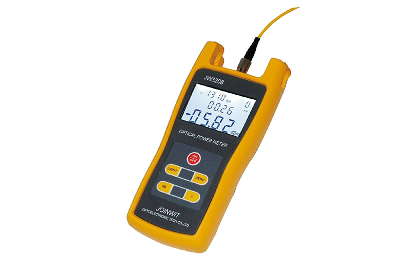
How to choose an optical power meter?
The most crucial consideration in selecting an optical power meter is matching the optical probe type with the expected operating range. How do we choose an appropriate optical power meter? The following four suggestions can help:
- Select the appropriate probe type and interface type
- Evaluate the accuracy and manufacture calibration procedures to match the range of fiber and splice requirements.
- Make sure the models are compatible with the measurement range and display resolution.
- It has the dB function of direct insertion loss measurement.
The optical probe is an essential component in the performance of an optical power meter. The optical probe is a solid-state photodiode that receives coupled light from the fiber optic network and converts it into an electrical signal. A connector interface or universal interface adapter can be used to input the probe. UCI accepts most industry-standard connectors
The calibration of the power meter is critical. For example, the fiber and connector performance standards align with the system requirements. Uncertainty may be present in the measurement values of different connection adapters. It is important to consider other potential error factors fully. Additionally, determining the type of optical power meter that matches the measurement range is vital. The measurement range is a comprehensive parameter that is expressed in dBm. It involves the evaluation of the minimum or maximum range of the input signal.
The dB function of optical power meters enables direct reading of optical loss, which is very useful. However, low-quality or low-cost optical power meters do not offer this function. The lack of dB function makes the process tiresome for the technician as they have to separately write down reference and measurement values to calculate the difference. Therefore, the dB function helps with productivity and minimizes calculation errors.
FAQ:
- Why is the test light of the optical power meter inaccurate?
- It may be due to the recent use of the optical power meter. An error in reference value occurs. Use the calibration method to fix the issue.
- The light-emitting device’s actual luminous value (DBM) is outside of the range. It is advised to purchase optical power between -50 and +20.
- In the case of an FC jumper, check the interface place and whether the raised part on the optical fiber FC port is in correct alignment with the notch of the optical power FC converter.
- Dust causes the optical power meter to become inaccurate after prolonged use. Wipe the interface with alcohol which usually solves the problem
- Why does the optical power meter number jump?
It is due to the high sensitivity of the optical power meter. A continuous light source will make the number jump, but a constant light source helps with stabilizing the value. The instrument needs to be returned if the optical power meter receives light but does not display any value despite being connected with the optical fiber.
- What wavelengths apply to the optical power meter?
The wavelength of the single-mode transceiver is 1310, 1550. The multi-mode transceiver is 850, whereas the optical transceiver is 1310.1550. The passive optical fiber network (PON) luminescence is 1490.1310.1550. The wavelength of the light emitted by an invisible red laser is 960.